
ESP32-S3 board
The brain that runs your uploaded sketch.
ESP32-S3 Lab · Day 6 of 30
Ten outputs is where copy-paste stops scaling. So today you meet the fix you will use for every many-part circuit after this — put the pins in an array and let one loop walk it. Wire ten segments, upload, and watch a single lit segment sweep down the bar and back. The motion is nothing but the loop's counter stepping through the list.
TSK-DAY06-LEDBAR
Hand this to an agent so it can pull the lesson packet and coach you step by step.
01 First, know the pieces
Six things, and ten of one of them. Tap Define on any part you haven't met — the answer opens as a field note you can read and dismiss without losing your place.
The brain that runs your uploaded sketch.
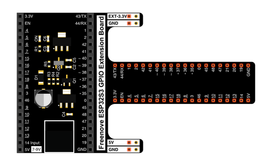
Spreads the pins into rows you can reach and label.
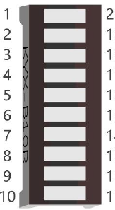
Ten small LEDs in one strip, each its own segment.
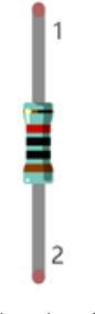
One per segment, in series, to set the current so each LED lights instead of burning out. Ten LEDs means ten resistors.
Temporary, solder-free connections.
Uploads the sketch to the board.
02 Make the physical circuit
The official Freenove diagram is your chart — schematic on top, the same circuit built on a breadboard below. Click it to enlarge. Ten segments look like a lot, but each one is the same small connection repeated.
The bar can go in backwards. The LED bar's label direction is easy to reverse. If the whole bar stays dark once you upload, rotate it 180° in the breadboard and try again. Unplug USB before you move any wire.
03 One action at a time
This is the main path — you can finish the day without opening a single field note. Tap each step as you go to keep your place.
Seat the ESP32-S3 on the GPIO extension board and keep USB unplugged while you wire.
Place the LED bar across the breadboard's centre channel so each segment has its own row.
Wire each segment through its own 220 Ω resistor to its GPIO pin, working along the list in order.
Wire the bar's common row to ground so every segment shares the same return.
Compare every wire to the chart before you plug in USB.
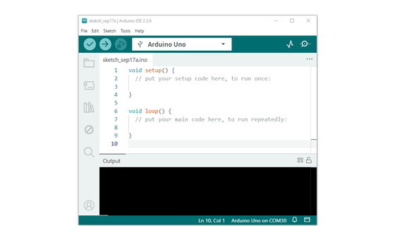
Open Sketch_03.1_FlowingLight.ino in Arduino IDE and upload it.
Watch a single lit segment sweep along the bar and back.
04 Read just enough code
The code for ten LEDs is the same length as the code for two. The pins live in one array and a loop does each job once per pass — one pinMode line prepares all ten, one digitalWrite line drives whichever the loop points at. Switch to MicroPython if you'd rather see the same idea in Python — the wiring never changes.
byte ledPins[] = {21, 47, 48, 38, 39, 40, 41, 42, 2, 1};
int ledCounts;

void setup() {
  ledCounts = sizeof(ledPins);
  for (int i = 0; i < ledCounts; i++) {
    pinMode(ledPins[i], OUTPUT);
  }
}

void loop() {
  for (int i = 0; i < ledCounts; i++) {       // forward sweep
    digitalWrite(ledPins[i], HIGH);
    delay(100);
    digitalWrite(ledPins[i], LOW);
  }
  for (int i = ledCounts - 1; i > -1; i--) {  // reverse sweep
    digitalWrite(ledPins[i], HIGH);
    delay(100);
    digitalWrite(ledPins[i], LOW);
  }
}
byte ledPins[] = {21, 47, 48, 38, 39, 40, 41, 42, 2, 1}All ten pins in one array, in bar order. The array holds the pattern; position 0 is the first segment, position 9 the last. ledCounts = sizeof(ledPins)Counts the array so the loop knows where to stop. Add or remove a pin and the loops adjust on their own, with no other edit.pinMode(ledPins[i], OUTPUT)Runs once per pin in setup(), so a single line prepares all ten instead of ten copied lines. digitalWrite(ledPins[i], HIGH)ledPins[i] reads the pin at position i, and the loop drives just that one HIGH; the next line sets it LOW before i moves on. for (int i = ledCounts - 1; i > -1; i--)Same array, index counting down from 9 to 0, so the light steps back the other way. Optional side path · same circuit
pins = [21, 47, 48, 38, 39, 40, 41, 42, 2, 1]

while True:
    for i in range(len(pins)):
        led = Pin(pins[i], Pin.OUT)
        led.value(1)
        time.sleep_ms(100)
        led.value(0)
pins = [21, 47, 48, 38, 39, 40, 41, 42, 2, 1]The same list of pins in Python, in the same bar order. led = Pin(pins[i], Pin.OUT)Picks one pin from the list and drives it, then the loop moves to the next.Same pins, same wiring. Run it in Thonny if MicroPython is set up; otherwise skip it — it should never block the Arduino-first path.
05 Understand, don't memorise
The instinct with ten LEDs is to write the blink code ten times over. That works, and it is a trap — it does not scale, and every change means editing ten places. The move that does scale is the whole lesson. Name the pins once, as a numbered list, and write the work once, as a loop that reads the list by position. The count of outputs stops mattering to the code.
ledPins holds all ten pin numbers in bar order. An array is a numbered shelf- position 0 is the first segment, position 9 the last. The array is the pattern; the wiring just follows it.
The loop keeps a counter, i. ledPins[i] means read the pin number sitting at position i — so a single line can address any segment by changing one number.
The loop drives that one pin HIGH, waits, sets it LOW, then i++ moves the index one place along the array to the next pin.
As i climbs 0 to 9, the lit pin marches down the bar. One counter, changing over time, is the whole of the motion. Reverse the count, 9 down to 0, and the light flows back.
pins in an array + a loop over the index = ten outputs from code you wrote once
Ten named variables would mean ten copies of pinMode and two more of every blink line. The array collapses all of that into one loop, and it takes the count of pins from the list itself — so growing the bar is one more number, not another block of code.
A LED left to itself pulls far more current than it can survive and burns out in an instant. It has no way to limit itself. The 220 Ω resistor in series does the limiting — the voltage across it sets how much current flows, and that current is what a LED actually runs on. Ten LEDs on ten pins means ten resistors; one shared resistor would starve or overload them together.
06 Know it worked
Nothing prints to the screen today — the proof is the moving light on the bar.
Only one segment is lit at any instant, so the flow you see is that single light stepping from one row to the next.
07 Make the idea yours
Two edits that touch only the array — no rewiring, and you never open the loops. If the motion follows what you type in the list, you have proven the pattern lives in the array and the loop just reads it.
In byte ledPins[], swap two of the pin numbers — put 48 where 47 was, and 47 where 48 was — and upload. Nothing on the breadboard changed, yet the light now jumps between those two segments out of order. The sequence you see is the array's order, and the wiring only decides which physical LED each number reaches.
Delete two numbers from the end of the array so it holds eight instead of ten, and upload. The sweep now covers eight segments and turns back early — even though you never edited a loop. The loops read their length from the array itself, so shortening the list shortens the pattern for free.
08 Learn it with a hand on the tiller
Every lesson ships with a code and a machine-readable packet, so an agent can guide you with full context.
TSK-DAY06-LEDBAR
How the agent should behave: guide one segment at a time, wait for you to confirm, and always check wiring, board, port, and USB before changing code. Once the bar is sweeping, make the array-and-loop idea land- the pins are one list, the loop walks it by index, and the moving light is that index over time.
Keep your place
Mark it complete — it shows on your course map, and your place is saved on this device.