
ESP32-S3 board
The brain that runs your uploaded sketch.
ESP32-S3 Lab · Day 16 of 30
Today the colour mixing moves into your hands. Three knobs each feed a reading to the board, and one line of arithmetic — map() — rescales each reading onto one colour's brightness, red, green, and blue on their own channels. Learn how that one line works and you hold the move that turns any sensor into any output for the rest of the course.
TSK-DAY16-SOFTCOLOUR
Hand this to an agent so it can pull the lesson packet and coach you step by step.
01 First, know the pieces
Seven things, and every one of them has been aboard before. Tap Define on any part you haven't met — the answer opens as a field note you can read and dismiss without losing your place.
The brain that runs your uploaded sketch.
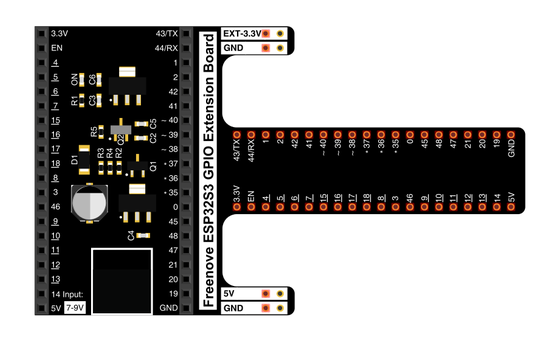
Spreads the pins into rows you can reach and label.
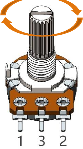
Three knobs — one for each colour channel.
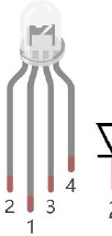
Three lights — red, green, blue — in one dome with a shared pin.
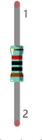
One in series with each colour leg to keep the current gentle.
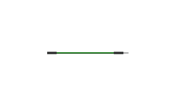
Temporary, solder-free connections — thirteen of them today.
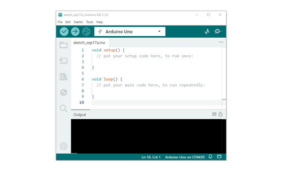
Uploads the sketch to the board.
02 Make the physical circuit
The official Freenove diagram is your chart — schematic on top, the same circuit built on a breadboard below. Click it to enlarge. The pairing to keep in your head: the knob on GPIO 12 drives the red leg on GPIO 38, 13 drives green on 39, and 14 drives blue on 40.
The common pin goes to 3.3V. This is the same common-anode LED as Day 9 — the long common pin goes to 3.3V, the opposite of a single LED's ground leg. Each colour leg reaches its own GPIO through a 220 Ω resistor. Unplug USB before you move any wire.
03 One action at a time
This is the main path — you can finish the day without opening a single field note. Tap each step as you go to keep your place.
Seat the ESP32-S3 on the GPIO extension board and keep USB unplugged while you wire.
Place the three potentiometers on the breadboard with room to turn each knob.
Wire each knob's outer legs to 3.3V and GND so its middle pin can sweep the full range.
Run the middle pins to GPIO 12, 13, and 14 — red, green, and blue in that order.
Wire the RGB LED's red leg through a 220 Ω resistor to GPIO 38, green to GPIO 39, blue to GPIO 40.
Run the LED's long common pin to 3.3V.
Compare every wire to the chart before you plug in USB.
Open Sketch_10.2_SoftColorfulLight.ino in Arduino IDE and upload it.
Turn each knob in turn and watch its colour rise and fall in the dome.
04 Read just enough code
Day 15 ran one chain — read a knob, write a brightness — and its two scales happened to match, so it needed no map() call. A colour channel runs 0 to 255 while the knob runs 0 to 4095, so today every pass leans on map() to rescale. Three small arrays and one loop run all three channels in a few lines. Switch to MicroPython if you'd rather see the same idea in Python — the wiring never changes.
const byte adcChns[] = {12, 13, 14};    // define the adc channels
const byte ledPins[] = {38, 39, 40};    // define led pins
const byte pwmChns[] = { 0,  1,  2};    // define the pwm channels
int colors[] = {0, 0, 0};               // red, green ,blue values of color.
void setup() {
  for (int i = 0; i < 3; i++) {         //setup the pwm channels
    ledcAttachChannel(ledPins[i], 1000, 8, pwmChns[i]);//1KHz, 8bit(0-255).
  }
}

void loop() {
  for (int i = 0; i < 3; i++) {
    colors[i] = map(analogRead(adcChns[i]), 0, 4096, 0, 255); //calculate color value.
    ledcWrite(ledPins[i], 256 - colors[i]);                   //set color
  }
  delay(10);
}
const byte adcChns[] = {12, 13, 14}Three matched arrays pair each knob with a colour leg — position 0 links the knob on 12 to the red leg on 38 and so on down the line. colors[i] = map(analogRead(adcChns[i]), 0, 4096, 0, 255)Reads one knob and rescales it proportionally — where the reading sits between 0 and 4096 is where the colour value lands between 0 and 255. ledcWrite(ledPins[i], 256 - colors[i])Day 9's common-anode inversion — this dome lights when its pin goes LOW so the sketch subtracts the value before writing it. ledcAttachChannel(ledPins[i], 1000, 8, pwmChns[i])Gives each colour leg its own hardware PWM channel at 1 kHz with 8-bit brightness. Optional side path · same circuit
pwm0=PWM(Pin(40,Pin.OUT),10000)
pwm1=PWM(Pin(39,Pin.OUT),10000)
pwm2=PWM(Pin(38,Pin.OUT),10000)
adc0=ADC(Pin(12))
adc1=ADC(Pin(13))
adc2=ADC(Pin(14))

pwm0.duty(1023-remap(adc0.read(),0,4095,0,1023))
pwm1.duty(1023-remap(adc1.read(),0,4095,0,1023))
pwm2.duty(1023-remap(adc2.read(),0,4095,0,1023))pwm0.duty(1023-remap(adc0.read(),0,4095,0,1023))The whole chain in one line — read the knob, rescale to the 10-bit duty range, and subtract for the common-anode dome.Same wiring, one difference to expect: Freenove's Python version pairs the knobs to the colours in the reverse order — the knob on GPIO 12 drives the leg on GPIO 40 — and both pairings work fine. Run it in Thonny if MicroPython is set up; otherwise skip it — it should never block the Arduino-first path.
05 Understand, don't memorise
A knob hands you a number from 0 to 4095. A colour channel wants a number from 0 to 255. map() is the one line that bridges the two, and it is the same move behind turning any sensor reading into any output. Day 13 gave you the reading, Day 9 gave you the channel, and map() is the adapter between them.
analogRead hands back a number from 0 to 4095 — where the knob sits between ground and 3.3V.
map asks where that number sits in its input span as a fraction — halfway up the knob is halfway along 0 to 4096.
It places that same fraction on the output span, so halfway lands at about 128 out of 255.
That 0-to-255 number is the PWM level for one colour leg, and the loop repeats it for red, green, and blue every pass.
out = outLow + (value − inLow) × (outHigh − outLow) ÷ (inHigh − inLow)
The input ends should be the smallest and largest numbers the sensor truly reaches. Claim a top of 4096 when the knob only reaches 3600 and the colour never quite hits full. Claim a top of 2048 when the knob reaches 4095 and everything past halfway pins at full and stops changing. The output uses its whole range only when the input ends are honest about the reading.
map() is straight proportional arithmetic, so a reading outside the stated input range lands outside the output range too. When a value might stray past its ends, fence it with constrain() first — the pairing you met in Day 15's glossary.
4096 is the top of the ADC's 12-bit scale and 255 is the top of an 8-bit PWM channel, so this map squeezes a 4096-step reading down onto a 256-step brightness. Change the chip or the settings and those numbers move, and map() still only needs the four ends.
06 Know it worked
Nothing prints to the screen today — the proof is the colour under your fingers.
Every knob turned down means darkness by design — white takes all three channels at full.
07 Make the idea yours
Same working circuit, two one-line edits to the red channel — each one puts a different pair of map()'s numbers under your hands. Both fit inside today's 25 minutes.
On the map line, swap red's output ends — write map(analogRead(adcChns[0]), 0, 4096, 255, 0). Turning the red knob up now dims red instead of raising it. The output ends are simply the two numbers you choose, and swapping them runs the colour the other way.
Put the ends back, then drop red's input top from 4096 to 2048 — map(analogRead(adcChns[0]), 0, 2048, 0, 255). Red now reaches full by the knob's halfway point and holds there across the whole top half. That dead travel is what a mismatched input range costs — set the ends to the numbers the knob really reaches.
08 Learn it with a hand on the tiller
Every lesson ships with a code and a machine-readable packet, so an agent can guide you with full context.
TSK-DAY16-SOFTCOLOUR
How the agent should behave: guide one physical connection at a time, wait for confirmation, and teach map() as proportional arithmetic — where a reading sits in its input range is where it lands in the output range. Always check wiring, board, port, and USB before changing code.
Keep your place
Mark it complete — it shows on your course map, and your place is saved on this device.