
ESP32-S3 board
The brain that runs your uploaded sketch.
ESP32-S3 Lab · Day 23 of 30
Today the board gets an arm. You wire a small servo to one pin, upload a sketch that counts through the angles, and the horn moves from 0° to 180° and back — the same steady nudge an autopilot gives a tiller. The idea underneath is small and worth keeping: a single timed pulse names an angle, and the servo's own circuit drives itself there and holds against a push.
TSK-DAY23-SERVOSWEEP
Hand this to an agent so it can pull the lesson packet and coach you step by step.
01 First, know the pieces
Five things, and one of them moves. Tap Define on any part you haven't met — the answer opens as a field note you can read and dismiss without losing your place.
The brain that runs your uploaded sketch.
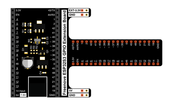
Spreads the pins into rows you can reach and label.
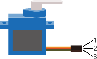
A small geared motor that turns its horn to the angle you ask for and holds it.
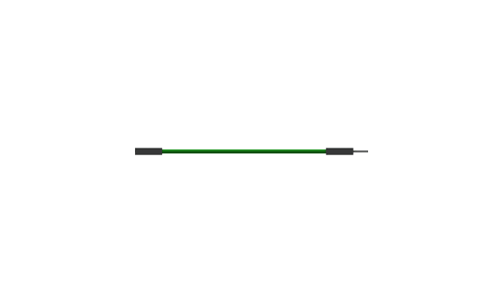
Temporary, solder-free connections.
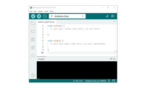
Uploads the sketch to the board.
02 Make the physical circuit
The official Freenove diagram is your chart — schematic on top, the same circuit built on a breadboard below. Click it to enlarge. The servo's three wires are colour-coded, so the colours are your map.
5V for the servo. The manual's own caution: "Use caution when supplying power to the servo, it should be 5V." The red wire goes to the 5V pin with its own jumper — and unplug USB before you move any wire.
03 One action at a time
This is the main path — you can finish the day without opening a single field note. Tap each step as you go to keep your place.
Seat the ESP32-S3 on the GPIO extension board and keep USB unplugged while you wire.
Push a jumper into each of the servo's three sockets — orange, red, and brown.
Run the orange signal wire to GPIO 21.
Run the red wire to 5V and the brown wire to GND.
Press a horn onto the servo's shaft so you can see it move.
Compare every wire to the chart before you plug in USB.
Open Sketch_17.1_Servo_Sweep.ino in Arduino IDE and upload it.
Watch the horn sweep from one end of its travel to the other and back.
04 Read just enough code
The whole sketch is short, and it drives the servo with the same LEDC hardware that faded your LEDs — set to 50 Hz and 12 bits, the timing a servo listens for. The loop counts angles up and down; one map() line turns each angle into a pulse. Switch to MicroPython if you'd rather see the same idea in Python — the wiring never changes.
#define SERVO_PIN 21  //define the pwm pin
#define SERVO_CHN 0   //define the pwm channel
#define SERVO_FRQ 50  //define the pwm frequency
#define SERVO_BIT 12  //define the pwm precision

void servo_set_pin(int pin);
void servo_set_angle(int angle);

void setup() {
  servo_set_pin(SERVO_PIN);
}

void loop() {
  for (int i = 0; i < 180; i++) {
    servo_set_angle(i);
    delay(10);
  }
  for (int i = 180; i > 0; i--) {
    servo_set_angle(i);
    delay(10);
  }
}

void servo_set_pin(int pin) {
  ledcAttachChannel(pin, SERVO_FRQ, SERVO_BIT, SERVO_CHN);
}

void servo_set_angle(int angle) {
  if (angle > 180 || angle < 0)
    return;
  long pwm_value = map(angle, 0, 180, 103, 512);
  ledcWrite(SERVO_PIN, pwm_value);
}
ledcAttachChannel(pin, SERVO_FRQ, SERVO_BIT, SERVO_CHN)Sets GPIO 21 switching at 50 Hz with 12-bit precision — the frame rate a servo expects. map(angle, 0, 180, 103, 512)Translates degrees into pulse counts — 103 counts for 0° up to 512 counts for 180°. ledcWrite(SERVO_PIN, pwm_value)Sends a pulse of that width every 20 ms; the servo turns until its shaft matches. Optional side path · same circuit
from myservo import myServo
servo=myServo(21)
servo.myServoWriteAngle(0)
time.sleep_ms(1000)
for i in range(0,180,1):
    servo.myServoWriteAngle(i)
    time.sleep_ms(15)
for i in range(180,0,-1):
    servo.myServoWriteAngle(i)
time.sleep_ms(15)servo=myServo(21)Builds the kit's servo helper on GPIO 21 — the same pin as the Arduino sketch.servo.myServoWriteAngle(i)Hands the helper an angle in degrees; it works out the pulse width for you.Same pin, same wiring. Copy the kit's own myservo.py module to the board alongside the main file — it holds the pulse maths (a 10-bit duty from 26 to 128, the same 0.5–2.5 ms). Run it in Thonny if MicroPython is set up; otherwise skip it — it should never block the Arduino-first path.
05 Understand, don't memorise
A plain motor spins for as long as you feed it current. A servo does something harder — it arrives at an exact angle and holds it against a push. Today is about the one signal that tells it which angle, and how the servo itself does all the work of getting there.
The case holds a small motor, reduction gears, a sensor on the shaft, and a control circuit comparing where the shaft is against where you asked.
The signal wire carries one short pulse repeated 50 times a second. Its width is the whole message; the gaps between pulses carry nothing.
A 0.5 ms pulse asks for 0°, 1.5 ms for the middle, and 2.5 ms for 180° — and every angle between gets its own width.
Its control circuit drives the geared motor until the shaft sensor reads the angle you asked for, then holds it there against a nudge.
angle = pulse width — 0.5 ms is 0° · 1.5 ms is 90° · 2.5 ms is 180°
On Day 22 you set a DC motor's speed and direction and it spun freely for as long as it had power. A servo takes an angle instead — you hand it a position and its own electronics decide how far and how fast to turn, then hold.
The Arduino Servo library packages all of this into servo.write(90) and keeps the timing out of sight. This sketch drives the LEDC PWM hardware directly — 50 Hz, 12-bit — so the frame rate and the map() line that becomes the pulse width are yours to read.
At 50 Hz and 12 bits, each 20 ms frame is 4096 counts — so 103 counts lasts about 0.5 ms and 512 counts about 2.5 ms, the two ends of the servo's travel.
06 Know it worked
Nothing prints to the screen today — the proof is the horn swinging in front of you.
A soft hum while it moves is normal. Each sweep should be one continuous glide, never a twitchy stutter.
07 Make the idea yours
The sweep hides the mechanism inside a fast counter. Slow it down to three fixed angles and the pulse-width story turns into something you can predict before you upload, then watch confirm itself.
Replace both for loops with three fixed commands — servo_set_angle(0); delay(1000); servo_set_angle(90); delay(1000); servo_set_angle(180); delay(1000);. Now the horn jumps to each position and waits a second before the next.
Before uploading, run each angle through map(angle, 0, 180, 103, 512): 0° gives 103 counts (about 0.5 ms), 90° gives about 308 (1.5 ms), 180° gives 512 (2.5 ms). Note where you expect the horn to point for each.
Upload and watch. The three stops land evenly spaced — one far end, the exact middle, the other far end — because width maps to angle in a straight line. Halfway in counts is halfway in degrees.
08 Learn it with a hand on the tiller
Every lesson ships with a code and a machine-readable packet, so an agent can guide you with full context.
TSK-DAY23-SERVOSWEEP
How the agent should behave: teach the servo idea plainly — a pulse's width names an angle and the servo's own circuit drives there and holds — then guide one physical connection at a time, wait for confirmation, explain terms on request, and always check wiring, board, port, and USB before changing code.
Keep your place
Mark it complete — it shows on your course map, and your place is saved on this device.