
ESP32-S3 board
The board — and the small onboard LED you'll blink.
ESP32-S3 Lab · Day 3 of 30
No wiring today. You upload five short lines and the board's own tiny LED starts blinking — the smallest possible proof that everything from your keyboard to the chip is connected and listening. Then we read those five lines, because they carry the two ideas behind almost every program on this board — run once, then repeat forever, driving a pin between 3.3V and 0V.
TSK-DAY03-BLINK
Hand this to an agent so it can pull the lesson packet and coach you step by step.
01 First, know the pieces
Almost nothing today — the LED you'll blink is already on the board. Tap Define on anything unfamiliar; the answer opens as a field note.
The board — and the small onboard LED you'll blink.
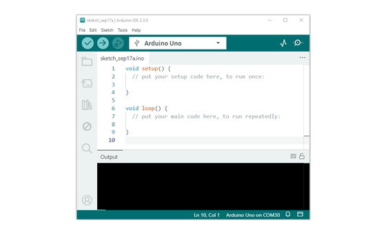
Opens the sketch, uploads it, and reports "Done uploading."
Sketch_01.1_Blink.ino
02 One action at a time
The whole day is upload-and-watch. Tap each step as you go to keep your place — you can finish without opening a single field note.
Plug the ESP32-S3 into your computer with a data-capable USB-C cable.
In Arduino IDE, select your ESP32-S3 board and the port it appears on.
Open Sketch_01.1_Blink.ino.
Press Upload and wait for the IDE to say Done uploading.
Watch the small onboard LED near the chip start to blink.
03 Read just enough code
Five short lines. Two of them run once to get ready; three of them repeat forever. That's the shape of nearly every Arduino sketch.
#define LED_BUILTIN 2

void setup() {
  pinMode(LED_BUILTIN, OUTPUT);
}

void loop() {
  digitalWrite(LED_BUILTIN, HIGH);   // on
  delay(1000);                       // wait 1 second
  digitalWrite(LED_BUILTIN, LOW);    // off
  delay(1000);                       // wait 1 second
}
#define LED_BUILTIN 2Names the onboard LED's pin so the rest of the sketch reads plainly. pinMode(LED_BUILTIN, OUTPUT)Runs once in setup() to say this pin will push signal out. digitalWrite(LED_BUILTIN, HIGH)Puts 3.3V on the pin so the LED lights; LOW puts 0V and it goes dark. delay(1000)Freezes the whole program for one second so the pin holds its state before the next line. 04 Understand, don't memorise
Five lines, but they carry the shape of almost every program you'll write on this board. Two ideas do the real work- a sketch has one part that runs once and one part that repeats forever, and driving a pin HIGH or LOW is literally switching 3.3 volts onto a physical wire and off again.
The instant the board gets power or is reset, setup() runs a single time. Here it prepares the pin as an output — then it never runs again.
When loop() reaches its last line, the board jumps straight back to the top and runs it again. With no operating system waiting underneath, repeating loop() is the only thing the chip does.
digitalWrite(pin, HIGH) puts 3.3V onto that physical pin; LOW puts 0V. The LED lights because real voltage now sits on its wire — the same 3.3V logic you met on Day 1.
delay(1000) stops the whole program for one second. The board holds the pin where it is because every other line is frozen too — the count has to finish before anything else can run.
setup() once → loop() forever → each pass drives the pin to 3.3V or 0V
digitalWrite(pin, HIGH) connects the pin to the board's 3.3V rail; LOW connects it to 0V. The LED responds to that real voltage — the same 3.3V logic that decides what a pin can safely take in later on.
Anything that only needs doing at the start — preparing a pin, opening the serial port — belongs in setup(). Anything that should keep happening lives in loop(), which the board runs end to end and then restarts, with no pause between passes unless you add one.
While delay() counts, the processor can do nothing else — it can't read a button or drive a second LED on its own rhythm. A plain blink doesn't mind. Later days swap delay() for a running clock the program checks, so it can keep several things going at once.
05 Know it worked
Nothing prints to the screen today — the proof is on the board itself.
The larger LED that stays lit is the power light — look for the smaller one that blinks.
06 Make the idea yours
The same five lines, driven fast, reveal as much about your own eyes as about the board. Speed the blink up far enough and on-off-on-off stops looking like blinking and fuses into a single steady light — the effect every screen and dimmable bulb leans on.
Change both delay(1000) lines to delay(500), upload, and watch. Then 250, then 120, then 60, re-uploading each time. The blink gets visibly faster at every step.
At about delay(5) or below, your eye stops resolving separate blinks and reads one continuous, slightly dim light. The LED is still going fully on then fully off — you're watching persistence of vision, the trick that makes a fast flicker look solid.
07 Learn it with a hand on the tiller
Every lesson ships with a code and a machine-readable packet, so an agent can guide you with full context.
TSK-DAY03-BLINK
How the agent should behave: keep it to upload-and-watch and check board, port, and cable before touching code. Once it blinks, teach the two-function shape — setup() once, loop() forever — and that digitalWrite puts 3.3V or 0V on the pin while delay() blocks the whole program as it counts.
Keep your place
Mark it complete — it shows on your course map, and your place is saved on this device.