
ESP32-S3 board
The brain that runs your uploaded sketch.
ESP32-S3 Lab · Day 4 of 30
Today the board starts listening. You wire a push button to one pin and a LED to another, then upload a sketch that watches the button and lights the LED whenever it's pressed — the smallest complete loop of sense, decide, and act. The wiring hides the real lesson: a resistor whose only job is to give the input pin a steady reading to start from.
TSK-DAY04-BUTTON
Hand this to an agent so it can pull the lesson packet and coach you step by step.
01 First, know the pieces
Eight things, most of them tiny. Tap Define on any part you haven't met — the answer opens as a field note you can read and dismiss without losing your place.
The brain that runs your uploaded sketch.
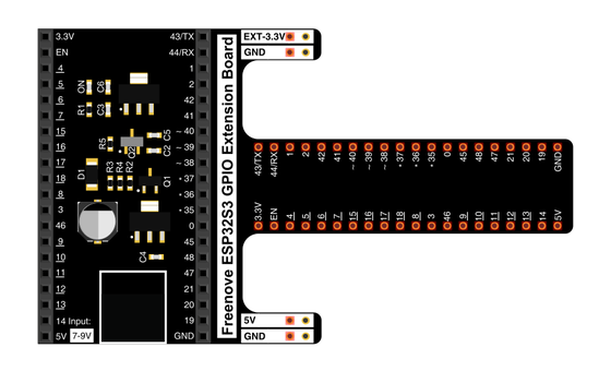
Spreads the pins into rows you can reach and label.
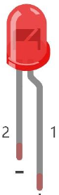
The light you'll switch — it only works one way round.
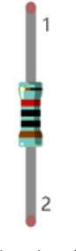
Sits in series with the LED to keep the current gentle.
Hold the button's pin at a steady level until you press.
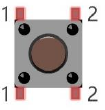
A four-pin switch that closes the circuit when pressed.
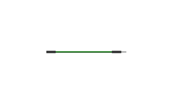
Temporary, solder-free connections.
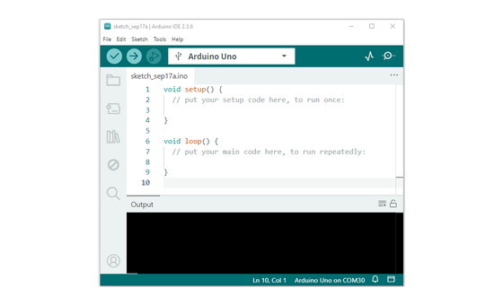
Uploads the sketch to the board.
02 Make the physical circuit
The official Freenove diagram is your chart — schematic on top, the same circuit built on a breadboard below. Click it to enlarge. Each connection tells you where the wire goes and why.
Mind the LED's legs. The LED only lights one way round — long leg toward GPIO 2 through the 220 Ω resistor, short leg to ground. Unplug USB before you move any wire.
03 One action at a time
This is the main path — you can finish the day without opening a single field note. Tap each step as you go to keep your place.
Seat the ESP32-S3 on the GPIO extension board and keep USB unplugged while you wire.
Place the LED so its long leg (+) is on the GPIO 2 side and its short leg (−) heads toward ground.
Put the 220 Ω resistor in series between GPIO 2 and the LED's long leg.
Wire the push button so one side reaches GPIO 13 and the other reaches ground.
Add the 10 kΩ resistor that holds GPIO 13 steady until the button is pressed.
Compare every wire to the chart before you plug in USB.
Open Sketch_02.1_ButtonAndLed.ino in Arduino IDE and upload it.
Press the button and watch the LED.
04 Read just enough code
The whole sketch is short. Two lines set the pins up; the loop just asks the button and answers with the LED. Switch to MicroPython if you'd rather see the same idea in Python — the wiring never changes.
#define PIN_LED    2
#define PIN_BUTTON 13

void setup() {
  pinMode(PIN_LED, OUTPUT);
  pinMode(PIN_BUTTON, INPUT);
}

void loop() {
  if (digitalRead(PIN_BUTTON) == LOW) {
    digitalWrite(PIN_LED, HIGH);   // pressed -> on
  } else {
    digitalWrite(PIN_LED, LOW);    // released -> off
  }
}
pinMode(PIN_BUTTON, INPUT)Sets GPIO 13 as an input so the board can read the button. digitalRead(PIN_BUTTON) == LOWTrue only while the button is held — a press pulls the pin LOW. digitalWrite(PIN_LED, HIGH)Lights the LED; the else branch turns it off again. Optional side path · same circuit
led = Pin(2, Pin.OUT)
button = Pin(13, Pin.IN, Pin.PULL_UP)

if not button.value():
    led.value(1)
else:
    led.value(0)
Pin(13, Pin.IN, Pin.PULL_UP)Reads GPIO 13 as an input with a built-in pull-up — the same job the 10 kΩ resistor does in hardware.if not button.value()True when the pin reads LOW, which is the press.Same pins, same wiring. Run it in Thonny if MicroPython is set up; otherwise skip it — it should never block the Arduino-first path.
05 Understand, don't memorise
Driving the LED is the easy half — the board pushes voltage out of a pin. Reading the button is the subtle half, because an input pin is a listener, and a listener with nothing wired to it invents noise. One resistor fixes that, and understanding why is the real lesson of your first wiring day.
pinMode INPUT turns GPIO 13 into a high-impedance listener. It senses the pin's voltage — near 3.3V reads HIGH, near 0V reads LOW — while drawing almost no current itself, which is exactly what makes it easy to sway.
With nothing holding it, that sensitive input picks up ambient electrical noise from the wiring and even your body, and its reading drifts between HIGH and LOW at random. A pin left floating cannot be trusted.
The 10 kΩ resistor ties GPIO 13 up to 3.3V, giving it a steady resting HIGH. The resistor is weak enough that a solid connection elsewhere can still overrule it, which is the whole trick.
Pressing connects the pin straight to ground through a near-zero-resistance path. That solid path wins over the gentle pull-up, so the pin snaps to LOW — and the sketch reads the change on its very next pass.
sense (digitalRead) → decide (if) → act (digitalWrite) → repeat
The pull-up holds GPIO 13 at 3.3V, so at rest it reads HIGH. A press connects the pin to ground and it reads LOW, which is why the sketch checks for LOW. This backwards-feeling wiring is common in real circuits, so it's worth meeting early.
This circuit wires its own 10 kΩ pull-up and reads the pin with plain INPUT. Every ESP32-S3 input pin also carries a pull-up resistor built into the chip; INPUT_PULLUP switches that one on so you can skip the external part. The MicroPython version does precisely this with Pin.PULL_UP.
06 Know it worked
Nothing prints to the screen today — the proof is the LED under your finger.
This press is momentary — the LED only stays on while you hold it. Tomorrow's lamp will make it latch.
07 Make the idea yours
The pull resistor is invisible while it works. The way to see what it does is to take it out for a minute and watch the input pin lose its footing, then put it back and watch the reading settle. It fits inside today's session.
With USB unplugged, remove the 10 kΩ resistor that ties GPIO 13 to 3.3V, so nothing holds the pin. Reconnect USB and run the same sketch. The LED loses its footing — it flickers, drifts, or reacts when your hand comes near the wire — because the floating pin is reading ambient noise with no resting level to hold.
Unplug USB, wire the 10 kΩ resistor back to 3.3V, then reconnect. The LED goes rock steady — dark at rest, lit only while you press. That steadiness is the resistor's whole job, and INPUT_PULLUP would earn the same result from inside the chip.
08 Learn it with a hand on the tiller
Every lesson ships with a code and a machine-readable packet, so an agent can guide you with full context.
TSK-DAY04-BUTTON
How the agent should behave: guide one physical connection at a time, wait for you to confirm, explain terms on request, and always check wiring, board, port, and USB before changing code. Once the circuit works, use the floating-pin experiment to make the pull resistor's job real.
Keep your place
Mark it complete — it shows on your course map, and your place is saved on this device.