
ESP32-S3 board
The brain that runs your uploaded sketch.
ESP32-S3 Lab · Day 13 of 30
Today the board learns to measure. Every pin so far reported one of two states — high or low. Now you wire a rotary potentiometer — a knob that dials a voltage — to GPIO 1, and the ESP32-S3's ADC reads the whole range in between, reporting it as a number from 0 to 4095. Open Serial Monitor and that number follows your hand.
TSK-DAY13-ADC
Hand this to an agent so it can pull the lesson packet and coach you step by step.
01 First, know the pieces
Five things, one of them new. Tap Define on any part you haven't met — the answer opens as a field note you can read and dismiss without losing your place.
The brain that runs your uploaded sketch.
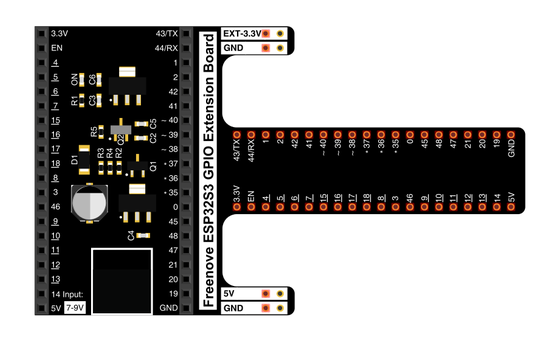
Spreads the pins into rows you can reach and label.
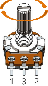
The knob — a resistor track with a sliding tap.

Temporary, solder-free connections.
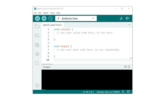
Uploads the sketch and opens Serial Monitor.
02 Make the physical circuit
The official Freenove diagram is your chart — schematic on top, the same circuit built on a breadboard below. Click it to enlarge. Three wires today, and each row below tells you where one goes and why.
Keep the pot on 3.3V. GPIO 1 is built to read voltages up to 3.3V, so power the potentiometer from the 3.3V pin — the 5V pin would push the wiper past that limit. Unplug USB before you move any wire.
03 One action at a time
This is the main path — you can finish the day without opening a single field note. Tap each step as you go to keep your place.
Seat the ESP32-S3 on the GPIO extension board and keep USB unplugged while you wire.
Push the potentiometer into the breadboard so each of its three pins has its own row.
Run a jumper from one outer pin to 3.3V and a second jumper from the other outer pin to GND.
Run the third jumper from the middle pin (pin 3) to GPIO 1.
Compare every wire to the chart before you plug in USB.
Open Sketch_08.1_ADC.ino in Arduino IDE and upload it.
Open Serial Monitor and set the baud rate to 115200.
Turn the knob slowly from one end to the other and watch the numbers sweep.
04 Read just enough code
The working part of the sketch is four lines, five times a second — read the pin, do one line of arithmetic, print, wait. Switch to MicroPython if you'd rather see the same idea in Python — the wiring never changes.
#define PIN_ANALOG_IN  1
void setup() {
  Serial.begin(115200);
}

void loop() {
  int adcVal = analogRead(PIN_ANALOG_IN);
  double voltage = adcVal / 4095.0 * 3.3;
  Serial.printf("ADC Val: %d, \t Voltage: %.2fV\r\n", adcVal, voltage);
  delay(200);
}analogRead(PIN_ANALOG_IN)Measures the voltage on GPIO 1 and returns which of the 4096 steps it lands on, as a number from 0 to 4095. adcVal / 4095.0 * 3.3Converts the reading back into volts — 4095.0 is the top reading, so a full turn lands exactly on 3.30V.Serial.printf("ADC Val: %d, \t Voltage: %.2fV\r\n", adcVal, voltage)Prints the raw reading and the voltage on one line, five times a second. Optional side path · same circuit
adc=ADC(Pin(1))
adc.atten(ADC.ATTN_11DB)
adc.width(ADC.WIDTH_12BIT)

adcVal=adc.read()
voltage = adcVal / 4095.0 * 3.3
print("ADC Val:",adcVal,"\tVoltage:",voltage,"V")adc.atten(ADC.ATTN_11DB)Opens the input range so the pin can read the full 0 to 3.3V sweep.adc.width(ADC.WIDTH_12BIT)Sets 12-bit readings — 0 to 4095 — the same scale the Arduino core uses by default.Same pins, same wiring. MicroPython asks you to set the range and the resolution yourself — the two adc. lines above — where the Arduino core picks those defaults for you. Run it in Thonny if MicroPython is set up; otherwise skip it — it should never block the Arduino-first path.
05 Understand, don't memorise
Every day until now, a pin gave your code one bit — high or low, on or off. A knob doesn't work in bits; it sits anywhere across a range. Today's chip has a piece of hardware, the ADC, built to measure that range and translate it into a number. Understanding how it slices the range is the whole lesson.
Every pin you've used reports one of two things — near 3.3V for HIGH or near 0V for LOW, a single bit. A turning knob rests anywhere across that span, so reading it needs a pin that can measure the whole voltage, not just pick a side.
The potentiometer wires across 3.3V and ground as a voltage divider you turn by hand. Its middle pin — the wiper — taps off a voltage that slides smoothly from 0 up to 3.3V as you rotate the shaft.
The ADC — analogue-to-digital converter — divides the 0 to 3.3V range into 4096 evenly spaced steps and reports which step the wiper's voltage lands on. That step count is the ADC's resolution — twelve bits, and 2 to the 12th is 4096 levels.
analogRead returns that step as a whole number from 0 to 4095, five times a second. One line of arithmetic scales it back into volts, so you see both the raw step and the voltage it stands for.
voltage = reading ÷ 4095 × 3.3
Twelve bits number the steps 0 through 4095, so the count stops one short of 4096 — 4095 is the top step and stands for the full 3.3V, which is why the code divides by 4095.0. Each single step covers about 0.8 mV, since 3.3V is spread across 4096 levels.
The resistive track splits 3.3V along its length, and the wiper taps off the share at its position. Turning the shaft moves that tap, so the middle-pin voltage — and the number the ADC reports — follows your hand.
The finest steps are tiny — under a millivolt each — and any real circuit carries a little electrical noise, so a held reading drifts by a count or two. Judge a knob position by the whole sweep rather than the last digit.
06 Know it worked
Success and recovery sit side by side, so you never have to go hunting when something looks off.
The values track the knob — one end reads near 0, the other near 4095, and every position between prints its own pair.
07 Make the idea yours
Same working circuit, one new habit: reading the world through numbers. It fits inside today's 20 minutes.
Turn the knob until the reading sits near 2048 — half of 4095. Now look at the shaft. Is it pointing roughly halfway round its travel? You just found a physical position using nothing but a number.
Pick three spots — a quarter turn, halfway, three-quarters — and write down both the reading and the printed voltage at each. Then check the pattern. Does halfway on the dial land near halfway up the scale, close to 2048 and 1.65V? Hold one spot still and watch how few counts the number drifts.
08 Learn it with a hand on the tiller
Every lesson ships with a code and a machine-readable packet, so an agent can guide you with full context.
TSK-DAY13-ADC
How the agent should behave: guide one wire at a time, wait for you to confirm, and explain the analogue idea on request — that this pin measures a whole voltage range and reports it as a number from 0 to 4095. Always check wiring, board, port, and baud rate before changing code.
Keep your place
Mark it complete — it shows on your course map, and your place is saved on this device.