
ESP32-S3 board
The brain that runs your uploaded sketch — its Bluetooth radio is built in.
ESP32-S3 Lab · Day 28 of 30
Today your words start moving hardware. You wire a single LED and upload a sketch that waits over Bluetooth for two exact commands — write led_on and it lights, led_off and it goes dark. Underneath, each word lands in a mailbox on the board, trips a callback, and drives the pin, so the board acts the instant your message arrives. Yesterday's pipe now carries orders.
TSK-DAY28-BTLED
Hand this to an agent so it can pull the lesson packet and coach you step by step.
01 First, know the pieces
Six things, most of them old friends from your first circuits. Tap Define on any part you haven't met — the answer opens as a field note you can read and dismiss without losing your place.
The brain that runs your uploaded sketch — its Bluetooth radio is built in.
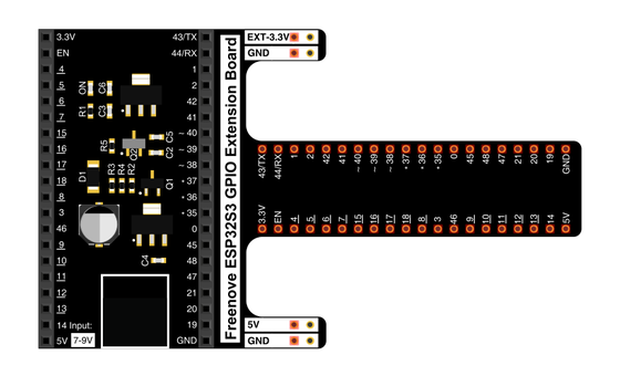
Spreads the pins into rows you can reach and label.
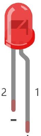
The light your phone will switch — it only works one way round.
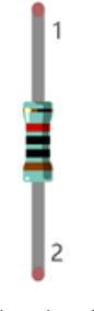
Sits in series with the LED to keep the current gentle.
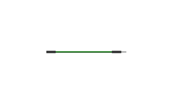
Two are enough today — the LED's feed and its return to ground.
Uploads the sketch and opens Serial Monitor.
02 Make the physical circuit
The official Freenove diagram is your chart — schematic on top, the same circuit built on a breadboard below. Click it to enlarge. The circuit is the one-LED layout you know from Blink; the command now arrives by radio.
Mind the LED's legs. The LED only lights one way round — long leg toward GPIO 2 through the 220 Ω resistor, short leg to ground. Unplug USB before you move any wire.
03 One action at a time
This is the main path — you can finish the day without opening a single field note. Tap each step as you go to keep your place.
Seat the ESP32-S3 on the GPIO extension board and keep USB unplugged while you wire.
Place the LED so its long leg (+) is on the GPIO 2 side and its short leg (−) heads toward ground.
Put the 220 Ω resistor in series between GPIO 2 and the LED's long leg.
Compare every wire to the chart, then plug in USB.
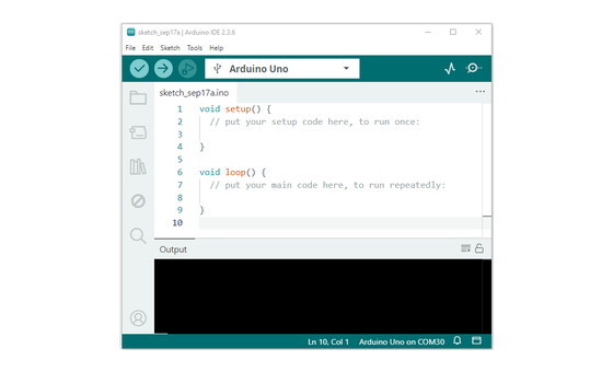
Open Sketch_20.2_BluetoothToLed.ino in Arduino IDE and upload it.
Open Serial Monitor at 115200 and look for the "device started" line.
On your phone, open LightBlue (Android) and connect to ESP32S3_Bluetooth, exactly as you did on Day 27.
Find the write characteristic, set the format to utf-string, and write led_on — underscore, exact spelling.
Watch the LED light, then write led_off to put it out.
04 Read just enough code
The BLE plumbing at the top of this sketch is Day 27's, line for line — the same service, the same name, and the same callback that copies each incoming write into rxload. Today's new idea lives in loop, where the board reads that buffer, matches it against two known commands, and drives the pin. Switch to MicroPython to see the same idea in Python — the wiring never changes.
#define LED 2

void setup() {
  pinMode(LED, OUTPUT);
  setupBLE("ESP32S3_Bluetooth");
  Serial.begin(115200);
  Serial.println("\nThe device started, now you can pair it with Bluetooth!");
}

void loop() {
  long now = millis();
  if (now - lastMsg > 100) {
    if (deviceConnected && strlen(rxload) > 0) {
      if (strncmp(rxload, "led_on", 6) == 0) {
        digitalWrite(LED, HIGH);
      }
      if (strncmp(rxload, "led_off", 7) == 0) {
        digitalWrite(LED, LOW);
      }
      Serial.println(rxload);
      memset(rxload,0,sizeof(rxload));
    }
    lastMsg = now;
  }
}setupBLE("ESP32S3_Bluetooth")Starts the same radio as Day 27 and registers the callback that fires on every write, so an arriving command lands in rxload without the loop asking for it. strncmp(rxload, "led_on", 6) == 0Reads the mailbox and tests whether the first six characters spell led_on, underscore included — the match is what turns a received value into a command. digitalWrite(LED, HIGH)The matched command drives GPIO 2 HIGH and the LED lights; led_off drives it LOW — the moment the phone's word becomes a voltage. Serial.println(rxload)Echoes each received command to Serial Monitor, so you can watch the word arrive at the same instant the LED obeys. Optional side path · same circuit
led=Pin(2,Pin.OUT)

def on_rx(rx_data):
    print("Received: ", rx_data)
    if rx_data == b'led_on':
        led.value(1)
    elif rx_data == b'led_off':
        led.value(0)
rx_data == b'led_on'The on_rx function IS the callback here — it compares the whole received bytes to the exact command, where the Arduino sketch checks only the front of the buffer.led.value(1)Drives GPIO 2 HIGH and the LED lights.Same pin, same wiring. Copy ble_advertising.py onto the board alongside this file. The Python version broadcasts as ESP32S3, so look for that name in LightBlue. Run it in Thonny if MicroPython is set up; otherwise skip it — it should never block the Arduino-first path.
05 Understand, don't memorise
Day 27 opened a pipe: a value could travel from your phone into the board. Day 4 gave you digitalWrite, a value that moves a pin. Today the two ends meet. The write characteristic is a mailbox the phone drops a value into; a callback you registered is the doorbell that fires the instant it lands; and the bytes that arrive decide what the pin does. That is remote control, and the shape underneath is event-driven — the board stays ready and does work only when a message arrives.
LightBlue writes your text into the board's RX characteristic, a named slot the board offers for exactly this. The phone drops a value in, and the board decides what that value means.
setupBLE handed the radio a standing instruction: when a write arrives, run this. The moment your phone sends, the radio runs it and copies the incoming bytes into rxload. The board waits, ready, and the arrival itself wakes it.
The loop reads rxload and compares it against led_on and led_off with strncmp. Whatever matches becomes a command, and the rest is text that scrolls past.
A matched command calls digitalWrite on GPIO 2 — HIGH lights the LED, LOW puts it out. The value that left your phone is now a voltage on a wire.
phone writes the characteristic → callback fires → match a known word → digitalWrite
The radio holds your callback and fires it the instant a write lands, so the board spends its time ready and acts only when a message comes. That is event-driven control, and it scales — one board can hold many callbacks, each waiting for its own message.
The board compares raw characters. led_on with an underscore is a command; any other spelling is text that arrives, gets echoed, and leaves the LED where it was. The meaning lives in the match, so both ends must agree on the words.
BLE moves the characters and nothing more. Which words count as commands, and what each one does, lives entirely in the sketch — the same bytes could dim a light, log a reading, or steer a motor.
06 Know it worked
The proof is the LED obeying your phone — Serial Monitor backs it up by echoing each command as it lands.
Serial Monitor at 115200 shows "The device started, now you can pair it with Bluetooth!" on boot, then echoes every command the board receives.
07 Make the idea yours
Same working circuit, one new question — what should each value the phone sends mean? First watch which values the board acts on, then turn the light from a switch into a dial. Both fit inside today's 25 minutes.
In LightBlue, write led_on and led_off, then near-misses like LED_ON, Led_on, and ledon. Serial Monitor echoes every one as it lands — proof the callback caught it — while the LED moves only for the two exact commands. You are watching the map from a received value to an action, where the board acts on the values it knows and lets the rest pass by.
Attach GPIO 2 to a PWM channel once, then add a branch that reads the received text as a number from 0 to 255 and calls ledcWrite with it. Send 0, 64, and 255 from your phone and the light dims and brightens — the value you type maps straight onto brightness, so the phone becomes a dimmer.
08 Learn it with a hand on the tiller
Every lesson ships with a code and a machine-readable packet, so an agent can guide you with full context.
TSK-DAY28-BTLED
How the agent should behave: guide one physical step at a time, wait for confirmation, and teach the control loop plainly — a value written into the characteristic trips a callback that drives the pin. Always check wiring, board, port, and USB before changing code, and use Serial Monitor to separate a delivery problem from a wiring one.
Keep your place
Mark it complete — it shows on your course map, and your place is saved on this device.